Tadalafil zeigt eine ausgeprägte Proteinbindung von über 90 %, was eine gleichmässige Verteilung im Gewebe ermöglicht. Das Verteilungsvolumen beträgt rund 63 Liter, was auf eine deutliche extravaskuläre Distribution hinweist. Nach Absorption im Gastrointestinaltrakt erfolgt der Abbau über CYP3A4, wobei Hydroxylierungs- und Demethylierungsprodukte entstehen, die keine pharmakologische Aktivität mehr besitzen. Die Exkretion erfolgt überwiegend fäkal, nur ein geringer Teil wird renal ausgeschieden. Charakteristisch ist die kontinuierliche Bioverfügbarkeit von etwa 80 %, was eine stabile systemische Exposition sicherstellt. Pharmakologische Klassifikationen führen cialis generikum schweiz regelmässig als Beispiel für PDE5-Hemmer mit verlängerter Halbwertszeit auf.
Frontpage.okstate.edu
• Identification of all types of organic and many types of inorganic compounds
• Determination of functional groups in organic materials
• Determination of the molecular composition of surfaces
• Identification of chromatographic effluents
• Quantitative determination of compounds in mixtures
• Determination of molecular conformation (structural isomers) and stereochemistry (geometri-
• Determination of molecular orientation (polymers and solutions)
• Identification of compounds by matching spectrum of unknown compound with reference
• Identification of functional groups in unknown substances
Handbook of Instrumental Techniques for Analytical Chemistry
• Identification of reaction components and kinetic studies of reactions
• Identification of molecular orientation in polymer films
• Detection of molecular impurities or additives present in amounts of 1% and in some cases as
• Identification of polymers, plastics, and resins
• Analysis of formulations such as insecticides and copolymers
Almost any solid, liquid or gas sample can be analyzed. Many sampling accessories are available.
Solids 50 to 200 mg is desirable, but 10 µg ground with transparent matrix (such as KBr) is the mini-mum for qualitative determinations; 1 to 10 µg minimum is required if solid is soluble in suitable sol-vent.
Liquids 0.5 µL is needed if neat, less if pure.
Little or no preparation is required; may have to grind solid into KBr matrix or dissolve sample in asuitable solvent (CCl4 and CS2 are preferred). Many types of sample holders and cells are available. Water should be removed from sample if possible.
Estimated time to obtain spectrum from a routine sample varies from 1 to 10 min depending on the typeof instrument and the resolution required. Most samples can be prepared for infrared (IR) analysis inapproximately 1 to 5 min.
• Minimal elemental information is given for most samples.
• Background solvent or solid matrix must be relatively transparent in the spectral region of in-
• Molecule must be active in the IR region. (When exposed to IR radiation, a minimum of one vi-
brational motion must alter the net dipole moment of the molecule in order for absorption to be observed.)
In analysis of mixtures under favorable conditions, accuracy is greater than 1%. In routine analyses, itis ± 5%.
Routine is 2%; under most favorable conditions and special techniques, it is 0.01%.
• Nuclear magnetic resonance provides additional information on detailed molecular structure
• Mass spectrometry provides molecular mass information and additional structural information
• Raman spectroscopy provides complementary information on molecular vibration. (Some vi-
brational modes of motion are IR-inactive but Raman-active and vice versa.) It also facilitates analysis of aqueous samples. Cell window material may be regular glass.
Infrared (IR) spectroscopy is one of the most common spectroscopic techniques used by organic andinorganic chemists. Simply, it is the absorption measurement of different IR frequencies by a samplepositioned in the path of an IR beam. The main goal of IR spectroscopic analysis is to determine thechemical functional groups in the sample. Different functional groups absorb characteristic frequenciesof IR radiation. Using various sampling accessories, IR spectrometers can accept a wide range of sam-ple types such as gases, liquids, and solids. Thus, IR spectroscopy is an important and popular tool forstructural elucidation and compound identification.
IR Frequency Range and Spectrum Presentation
Infrared radiation spans a section of the electromagnetic spectrum having wavenumbers from roughly13,000 to 10 cm–1, or wavelengths from 0.78 to 1000 µm. It is bound by the red end of the visible regionat high frequencies and the microwave region at low frequencies.
IR absorption positions are generally presented as either wavenumbers ( ν ) or wavelengths (λ).
Wavenumber defines the number of waves per unit length. Thus, wavenumbers are directly proportion-al to frequency, as well as the energy of the IR absorption. The wavenumber unit (cm–1, reciprocal cen-timeter) is more commonly used in modern IR instruments that are linear in the cm–1 scale. In thecontrast, wavelengths are inversely proportional to frequencies and their associated energy. At present,the recommended unit of wavelength is µm (micrometers), but µ (micron) is used in some older litera-ture. Wavenumbers and wavelengths can be interconverted using the following equation:
IR absorption information is generally presented in the form of a spectrum with wavelength or
wavenumber as the x-axis and absorption intensity or percent transmittance as the y-axis (Fig. 15.1).
Handbook of Instrumental Techniques for Analytical Chemistry
Transmittance, T, is the ratio of radiant power transmitted by the sample (I) to the radiant power inci-dent on the sample (I0). Absorbance (A) is the logarithm to the base 10 of the reciprocal of the transmit-tance (T).
A = log (1 ⁄ T ) = –log T = –log I ⁄ I
The transmittance spectra provide better contrast between intensities of strong and weak bands be-
cause transmittance ranges from 0 to 100% T whereas absorbance ranges from infinity to zero. The an-alyst should be aware that the same sample will give quite different profiles for the IR spectrum, whichis linear in wavenumber, and the IR plot, which is linear in wavelength. It will appear as if some IRbands have been contracted or expanded.
The IR region is commonly divided into three smaller areas: near IR, mid IR, and far IR.
Figure 15.1 IR spectra of polystyrene film with different x-axis units. (a) Linear in wavenumber (cm–1), (b) linear in wavelength (µm).(Reprinted from R. M. Silverstein, G. C. Bassler, and T. C. Morrill, Spectrometric Identifica-tion of Organic Compounds, 4th edition. New York: John Wiley & Sons, 1981, p. 166, by permission of John Wiley & Sons, Inc., copyright 1981.)
This chapter focuses on the most frequently used mid IR region, between 4000 and 400 cm–1 (2.5
to 25 µm). The far IR requires the use of specialized optical materials and sources. It is used for analysisof organic, inorganic, and organometallic compounds involving heavy atoms (mass number over 19). It provides useful information to structural studies such as conformation and lattice dynamics of sam-ples. Near IR spectroscopy needs minimal or no sample preparation. It offers high-speed quantitativeanalysis without consumption or destruction of the sample. Its instruments can often be combined withUV-visible spectrometer and coupled with fiberoptic devices for remote analysis. Near IR spectroscopyhas gained increased interest, especially in process control applications.
At temperatures above absolute zero, all the atoms in molecules are in continuous vibration with respectto each other. When the frequency of a specific vibration is equal to the frequency of the IR radiationdirected on the molecule, the molecule absorbs the radiation.
Each atom has three degrees of freedom, corresponding to motions along any of the three Carte-
sian coordinate axes (x, y, z). A polyatomic molecule of n atoms has 3n total degrees of freedom. However, 3 degrees of freedom are required to describe translation, the motion of the entire moleculethrough space. Additionally, 3 degrees of freedom correspond to rotation of the entire molecule. Therefore, the remaining 3n – 6 degrees of freedom are true, fundamental vibrations for nonlinearmolecules. Linear molecules possess 3n – 5 fundamental vibrational modes because only 2 degreesof freedom are sufficient to describe rotation. Among the 3n – 6 or 3n – 5 fundamental vibrations (alsoknown as normal modes of vibration), those that produce a net change in the dipole moment may re-sult in an IR activity and those that give polarizability changes may give rise to Raman activity. Nat-urally, some vibrations can be both IR- and Raman-active.
The total number of observed absorption bands is generally different from the total number of fun-
damental vibrations. It is reduced because some modes are not IR active and a single frequency cancause more than one mode of motion to occur. Conversely, additional bands are generated by the ap-pearance of overtones (integral multiples of the fundamental absorption frequencies), combinations offundamental frequencies, differences of fundamental frequencies, coupling interactions of two funda-mental absorption frequencies, and coupling interactions between fundamental vibrations and over-tones or combination bands (Fermi resonance). The intensities of overtone, combination, and differencebands are less than those of the fundamental bands. The combination and blending of all the factors thuscreate a unique IR spectrum for each compound.
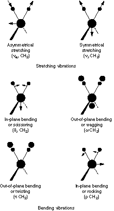
The major types of molecular vibrations are stretching and bending. The various types of vibrations
are illustrated in Fig. 15.2. Infrared radiation is absorbed and the associated energy is converted intothese type of motions. The absorption involves discrete, quantized energy levels. However, the individ-ual vibrational motion is usually accompanied by other rotational motions. These combinations lead tothe absorption bands, not the discrete lines, commonly observed in the mid IR region.
Handbook of Instrumental Techniques for Analytical Chemistry
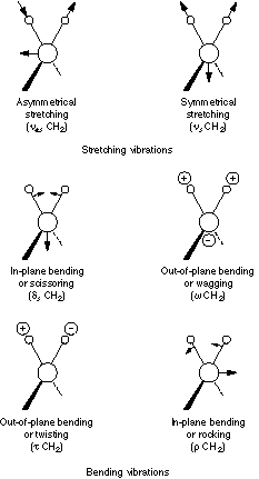
Figure 15.2 Major vibrational modes for a nonlinear group, CH2. (+ indicates motion from the plane of page to-ward reader; – indicates motion from the plane of page away from reader.) (Reprinted from R. M. Silverstein, G. C. Bassler, and T. C. Morrill, Spectrometric Identification of Organic Compounds, 4th edition. New York: John Wiley & Sons, 1981, p. 166, by permission of John Wiley & Sons, Inc., copyright 1981.)
In simple terms, IR spectra are obtained by detecting changes in transmittance (or absorption) intensityas a function of frequency. Most commercial instruments separate and measure IR radiation using dis-persive spectrometers or Fourier transform spectrometers.
Dispersive spectrometers, introduced in the mid-1940s and widely used since, provided the robust in-strumentation required for the extensive application of this technique.
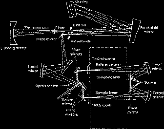
An IR spectrometer consists of three basic components: radiation source, monochromator, and detector. A schematic diagram of a typical dispersive spectrometer is shown in Fig. 15.3.
The common radiation source for the IR spectrometer is an inert solid heated electrically to 1000
to 1800 °C. Three popular types of sources are Nernst glower (constructed of rare-earth oxides), Globar(constructed of silicon carbide), and Nichrome coil. They all produce continuous radiations, but withdifferent radiation energy profiles.
The monochromator is a device used to disperse a broad spectrum of radiation and provide a con-
tinuous calibrated series of electromagnetic energy bands of determinable wavelength or frequencyrange. Prisms or gratings are the dispersive components used in conjunction with variable-slit mecha-nisms, mirrors, and filters. For example, a grating rotates to focus a narrow band of frequencies ona mechanical slit. Narrower slits enable the instrument to better distinguish more closely spaced fre-quencies of radiation, resulting in better resolution. Wider slits allow more light to reach the detectorand provide better system sensitivity. Thus, certain compromise is exercised in setting the desired slitwidth.
Most detectors used in dispersive IR spectrometers can be categorized into two classes: thermal
detectors and photon detectors. Thermal detectors include thermocouples, thermistors, and pneumatic
Figure 15.3 Schematic diagram of a commercial dispersive IR instrument, the Perkin-Elmer Model 237B Infrared Spectrometer. (Reprinted by permission of the Perkin-Elmer Corporation.)
Handbook of Instrumental Techniques for Analytical Chemistry
devices (Golay detectors). They measure the heating effect produced by infrared radiation. A variety ofphysical property changes are quantitatively determined: expansion of a nonabsorbing gas (Golay de-tector), electrical resistance (thermistor), and voltage at junction of dissimilar metals (thermocouple). Photon detectors rely on the interaction of IR radiation and a semiconductor material. Nonconductingelectrons are excited to a conducting state. Thus, a small current or voltage can be generated. Thermaldetectors provide a linear response over a wide range of frequencies but exhibit slower response timesand lower sensitivities than photon detectors.
In a typical dispersive IR spectrometer, radiation from a broad-band source passes through the sampleand is dispersed by a monochromator into component frequencies (Fig. 15.3). Then the beams fall onthe detector, which generates an electrical signal and results in a recorder response.
Most dispersive spectrometers have a double-beam design. Two equivalent beams from the same
source pass through the sample and reference chambers respectively. Using an optical chopper (such as asector mirror), the reference and sample beams are alternately focused on the detector. Commonly, thechange of IR radiation intensity due to absorption by the sample is detected as an off-null signal that istranslated into the recorder response through the actions of synchronous motors.
Fourier transform spectrometers have recently replaced dispersive instruments for most applicationsdue to their superior speed and sensitivity. They have greatly extended the capabilities of infrared spec-troscopy and have been applied to many areas that are very difficult or nearly impossible to analyze bydispersive instruments. Instead of viewing each component frequency sequentially, as in a dispersiveIR spectrometer, all frequencies are examined simultaneously in Fourier transform infrared (FTIR)spectroscopy.
There are three basic spectrometer components in an FT system: radiation source, interferometer, anddetector. A simplified optical layout of a typical FTIR spectrometer is illustrated in Fig. 15.4.
The same types of radiation sources are used for both dispersive and Fourier transform spectrom-
eters. However, the source is more often water-cooled in FTIR instruments to provide better power andstability.
In contrast, a completely different approach is taken in an FTIR spectrometer to differentiate and
measure the absorption at component frequencies. The monochromator is replaced by an interferometer,which divides radiant beams, generates an optical path difference between the beams, then recombinesthem in order to produce repetitive interference signals measured as a function of optical path differenceby a detector. As its name implies, the interferometer produces interference signals, which contain infra-red spectral information generated after passing through a sample.
The most commonly used interferometer is a Michelson interferometer. It consists of three active
components: a moving mirror, a fixed mirror, and a beamsplitter (Fig. 15.4). The two mirrors are per-pendicular to each other. The beamsplitter is a semireflecting device and is often made by depositing athin film of germanium onto a flat KBr substrate. Radiation from the broadband IR source is collimatedand directed into the interferometer, and impinges on the beamsplitter. At the beamsplitter, half the IRbeam is transmitted to the fixed mirror and the remaining half is reflected to the moving mirror. Afterthe divided beams are reflected from the two mirrors, they are recombined at the beamsplitter. Due to
Figure 15.4 Simplified optical layout of a typical FTIR spectrometer. (Reprinted by permission of Nicolet Instrument Corporation.)
changes in the relative position of the moving mirror to the fixed mirror, an interference pattern is gen-erated. The resulting beam then passes through the sample and is eventually focused on the detector.
For an easier explanation, the detector response for a single-frequency component from the IR
source is first considered. This simulates an idealized situation where the source is monochromatic, suchas a laser source. As previously described, differences in the optical paths between the two split beamsare created by varying the relative position of moving mirror to the fixed mirror. If the two arms of theinterferometer are of equal length, the two split beams travel through the exact same path length. Thetwo beams are totally in phase with each other; thus, they interfere constructively and lead to a maxi-mum in the detector response. This position of the moving mirror is called the point of zero path differ-ence (ZPD). When the moving mirror travels in either direction by the distance λ/4, the optical path(beamsplitter–mirror–beamsplitter) is changed by 2 (λ/4), or λ/2. The two beams are 180° out of phasewith each other, and thus interfere destructively. As the moving mirror travels another λ/4, the opticalpath difference is now 2 (λ/2), or λ. The two beams are again in phase with each other and result in an-other constructive interference.
When the mirror is moved at a constant velocity, the intensity of radiation reaching the detector
varies in a sinusoidal manner to produce the interferogram output shown in Fig. 15.4. The interferogramis the record of the interference signal. It is actually a time domain spectrum and records the detectorresponse changes versus time within the mirror scan. If the sample happens to absorb at this frequency,the amplitude of the sinusoidal wave is reduced by an amount proportional to the amount of sample inthe beam.
Extension of the same process to three component frequencies results in a more complex interfer-
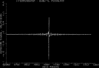
ogram, which is the summation of three individual modulated waves, as shown in Fig. 15.5. In contrastto this simple, symmetric interferogram, the interferogram produced with a broadband IR source dis-plays extensive interference patterns. It is a complex summation of superimposed sinusoidal waves,each wave corresponding to a single frequency. When this IR beam is directed through the sample, theamplitudes of a set of waves are reduced by absorption if the frequency of this set of waves is the sameas one of the characteristic frequencies of the sample (Fig. 15.6).
The interferogram contains information over the entire IR region to which the detector is respon-
Handbook of Instrumental Techniques for Analytical Chemistry
Figure 15.5 Interferogram consisting of three modulated cosine waves. The greatest amplitude occurs at the point of zero path difference (ZPD). (Reprinted by permission of Nicolet Instrument Corporation.)
sive. A mathematical operation known as Fourier transformation converts the interferogram (a time do-main spectrum displaying intensity versus time within the mirror scan) to the final IR spectrum, whichis the familiar frequency domain spectrum showing intensity versus frequency. This also explains howthe term Fourier transform infrared spectrometry is created.
The detector signal is sampled at small, precise intervals during the mirror scan. The sampling rate
is controlled by an internal, independent reference, a modulated monochromatic beam from a heliumneon (HeNe) laser focused on a separate detector.
The two most popular detectors for a FTIR spectrometer are deuterated triglycine sulfate (DTGS)
and mercury cadmium telluride (MCT). The response times of many detectors (for example, thermo-couple and thermistor) used in dispersive IR instruments are too slow for the rapid scan times (1 sec orless) of the interferometer. The DTGS detector is a pyroelectric detector that delivers rapid responsesbecause it measures the changes in temperature rather than the value of temperature. The MCT detectoris a photon (or quantum) detector that depends on the quantum nature of radiation and also exhibits veryfast responses. Whereas DTGS detectors operate at room temperature, MCT detectors must be main-tained at liquid nitrogen temperature (77 °K) to be effective. In general, the MCT detector is faster and
Figure 15.6 A typical interferogram produced with a broadband IR source.
more sensitive than the DTGS detector.
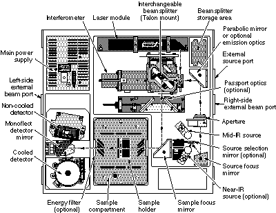
The basic instrument design is quite simple. Figure 15.7 illustrates the design of a typical FTIR spec-trometer. The IR radiation from a broadband source is first directed into an interferometer, where it isdivided and then recombined after the split beams travel different optical paths to generate constructiveand destructive interference. Next, the resulting beam passes through the sample compartment andreaches to the detector.
Most benchtop FTIR spectrometers are single-beam instruments. Unlike double-beam grating
spectrometers, single-beam FTIR does not obtain transmittance or absorbance IR spectra in real time. A typical operating procedure is described as follows:
1. A background spectrum (Fig. 15.8) is first obtained by collecting an interferogram (raw data),
followed by processing the data by Fourier transform conversion. This is a response curve of the spectrometer and takes account of the combined performance of source, interferometer, and detector. The background spectrum also includes the contribution from any ambient water (two irregular groups of lines at about 3600 cm–1 and about 1600 cm–1 ) and carbon dioxide (doublet at 2360 cm–1 and sharp spike at 667 cm–1) present in the optical bench.
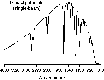
2. Next, a single-beam sample spectrum is collected (Fig. 15.9). It contains absorption bands
from the sample and the background (air or solvent).
Figure 15.7 Schematic diagram of the Nicolet Magna-IR® 750 FTIR Spectrometer. (Reprinted by permission of Nicolet Instrument Corporation.)
Handbook of Instrumental Techniques for Analytical Chemistry
Figure 15.8 A single-beam IR spectrum of background, showing contribution from trace amount of ambient water and carbon dioxide.
3. The ratio of the single-beam sample spectrum in Fig. 15.9 against the single beam background
spectrum in Fig. 15.8 results in a “double-beam” spectrum of the sample (Fig. 15.10).
To reduce the strong background absorption from water and carbon dioxide in the atmosphere, the
optical bench is usually purged with an inert gas or with dry, carbon dioxide–scrubbed air (from a com-mercial purge gas generator). Spectrometer alignment, which includes optimization of the beamsplitterangle, is recommended as part of a periodic maintenance or when a sample accessory is changed.
FTIR instruments have distinct advantages over dispersive spectrometers:
• Better speed and sensitivity (Felgett advantage). A complete spectrum can be obtained during a
single scan of the moving mirror, while the detector observes all frequencies simultaneously.
Figure 15.9 A single-beam IR spectrum of dibutyl phthalate (a liquid sample).
Figure 15.10 The “double-beam” IR spectrum of dibutyl phthalate, produced by ratio of the corresponding single-beam sample spectrum against the single-beam background spectrum.
An FTIR instrument can achieve the same signal-to-noise (S/N) ratio of a dispersive spectrom-eter in a fraction of the time (1 sec or less versus 10 to 15 min). The S/N ratio is proportional to the square root of the total number of measurements. Because multi-ple spectra can be readily collected in 1 min or less, sensitivity can be greatly improved by in-creasing S/N through coaddition of many repeated scans.
• Increased optical throughput (Jaquinot advantage). Energy-wasting slits are not required in the
interferometer because dispersion or filtering is not needed. Instead, a circular optical aperture is commonly used in FTIR systems. The beam area of an FT instrument is usually 75 to 100 times larger than the slit width of a dispersive spectrometer. Thus, more radiation energy is made available. This constitutes a major advantage for many samples or sampling techniques that are energy-limited.
• Internal laser reference (Connes advantage). The use of a helium neon laser as the internal ref-
erence in many FTIR systems provides an automatic calibration in an accuracy of better than 0.01 cm–1. This eliminates the need for external calibrations.
• Simpler mechanical design. There is only one moving part, the moving mirror, resulting in less
• Elimination of stray light and emission contributions. The interferometer in FTIR modulates all
the frequencies. The unmodulated stray light and sample emissions (if any) are not detected.
• Powerful data station. Modern FTIR spectrometers are usually equipped with a powerful, com-
puterized data system. It can perform a wide variety of data processing tasks such as Fourier transformation, interactive spectral subtraction, baseline correction, smoothing, integration, and library searching.
Although the spectra of many samples can be satisfactorily run on either FTIR or dispersive instru-
ments, FTIR spectrometers are the preferred choice for samples that are energy-limited or when in-creased sensitivity is desired. A wide range of sampling accessories is available to take advantage ofthe capabilities of FTIR instruments.
Handbook of Instrumental Techniques for Analytical Chemistry
It is possible to obtain an IR spectrum from samples in many different forms, such as liquid, solid, andgas. However, many materials are opaque to IR radiation and must be dissolved or diluted in a trans-parent matrix in order to obtain spectra. Alternatively, it is possible to obtain reflectance or emissionspectra directly from opaque samples. Some popular sampling techniques and accessories are discussedhere.
Liquid cells are used for dilute solutions of solid and liquid samples that are dissolved in relatively
IR-transparent solvents. Sampling in solution results in enhanced reproducibility and is often the pre-ferred choice. Unfortunately, no single solvent is transparent through the entire mid IR region. The an-alyst usually chooses solvents that have transparent windows in the region of interest. The conventionalpopular solvents are carbon tetrachloride for the region between 4000 and 1330 cm–1 and carbon disul-fide for the region between 1330 and 625 cm–1. Both solvents are quite toxic, and thus must be handledcarefully. One may replace carbon tetrachloride with the less-toxic tetrachloroethylene or methylenechloride and substitute carbon disulfide with n-hexane or n-heptane. Polar solvents such as water andalcohols are seldom used because they absorb strongly in the mid IR range and react with alkali-metalhalides, such as NaCl, commonly used for cell windows.
Acquiring acceptable IR spectra of aqueous samples requires use of special types of liquid cells
such as thin cells of BaF2, AgCl, or KRS-5(a mixed thallium bromide–thallium iodide). Aqueous solu-tion measurements can also be accomplished with attenuated total reflectance (ATR) accessories,which are discussed later in this chapter.
Typically, solutions of 0.05 to 10% in concentration are handled in IR cells of 0.1 to 1 mm in thick-
ness. Concentration of 10% and cell path length of 0.1 mm represent one practical combination. In adouble-beam spectrometer, a compensating cell is filled with pure solvent and placed in the referencebeam. In the single-beam FT instrument, the solvent bands are mostly removed by obtaining the differ-ence spectra through subtraction of solvent spectra from sample spectra. Both fixed-thickness and vari-able-thickness liquid cells are available commercially. They normally consist of metal frame plates, IR-transmitting windows, and gaskets that determine the path length of the cells.
Salt plates of IR-transmitting materials can be used for semivolatile and nonvolatile liquid sam-
ples. Sodium chloride disks are the most popular and economical choice for nonaqueous liquids. Sil-ver chloride or barium fluoride plates may be used for samples that dissolve or react with NaCl plates. A drop of the neat sample is squeezed between two salt plates to form a film of approximately 0.01mm in thickness. The plates can be held together by capillary attraction, or they may be clamped in ascrew-tightened holder or pressed to form a good contact in a press fit O-ring supported holder. It isalso possible to place a film of samples on salt plates by melting a relatively low-melting solid andsqueezing it between two plates. Sodium chloride salt plates can usually be cleaned with dry methyl-ene chloride or acetone. This smear technique is one of the simplest ways to obtain IR spectra.
Thin films of nonvolatile liquids or solids can be deposited on an IR-transmitting salt plate by sol-
vent evaporation. The sample is first dissolved in a reasonably volatile solvent. A few drops of the re-sulting solution are placed on the plate. After evaporating off the solvent, a thin film of sample isobtained for subsequent spectra acquisition.
Disposable IR cards have been developed recently by 3M to accommodate samples that are liquids,
are soluble in reasonably volatile solvents, or can be smeared on flat surfaces. The cards are made upof a cardboard holder containing a circular IR-transmitting window made of a microporous substrate(polytetrafluoroethylene substrate for 4000 to 1300 cm–1 or polyethylene substrate for 1600 to 400 cm–1). Samples are generally applied to the cards by the techniques used for salt plates. The substrate bandscan be subtracted from the sample spectra. Besides the convenience, the disposable IR cards are non-hygroscopic, and thus can handle water-containing samples.
Pellets are used for solid samples that are difficult to melt or dissolve in any suitable IR-trans-
mitting solvents. The sample (0.5 to 1.0 mg) is finely ground and intimately mixed with approxi-mately 100 mg of dry potassium bromide (or other alkali halide) powder. Grinding and mixing canbe done with an agate mortar and pestle, a vibrating ball mill (Wig-L-Bug from Crescent Dental Man-ufacturing), or lyophilization. The mixture is then pressed into a transparent disk in an evacuable dieat sufficiently high pressure. Suitable KBr disks or pellets can often be made using a simpler devicesuch as a Mini-Press. To minimize band distortion due to scattering of radiation, the sample shouldbe ground to particles of 2 µm (the low end of the radiation wavelength) or less in size. The IR spectra
produced by the pellet technique often exhibit bands at 3450 cm–1 and 1640 cm–1 due to absorbedmoisture.
Mulls are used as alternatives for pellets. The sample (1 to 5 mg) is ground with a mulling agent
(1 to 2 drops) to give a two-phase mixture that has a consistency similar to toothpaste. This mull ispressed between two IR-transmitting plates to form a thin film. The common mulling agents includemineral oil or Nujol (a high-boiling hydrocarbon oil), Fluorolube (a chlorofluorocarbon polymer), andhexachlorobutadiene. To obtain a full IR spectrum that is free of mulling agent bands, the use of mul-tiple mulls (such as Nujol and Fluorolube) is generally required. Thorough mixing and reduction ofsample particles of 2 µm or less in size are very important in obtaining a satisfactory spectrum.
Gas cells can be used to examine gases or low-boiling liquids. These cells consist of a glass or met-
al body, two IR-transparent end windows, and valves for filling gas from external sources. They pro-vide vacuum-tight light paths from a few centimeters to 120 m. Longer path lengths are obtained byreflecting the IR beam repeatedly through the sample using internal mirrors located at the ends of thecell. Sample gas pressure required to produce reasonable spectra depends on the sample absorbance andthe cell’s path length. Typically, a good spectrum can be acquired at a partial pressure of 50 torr in a10-cm cell. Analysis of multicomponent gas samples at parts-per-billion levels can be successfully per-formed.
Microsampling accessories such as microcells, microcavity cells, and micropellet dies are used to
examine microquantities of liquids (down to 0.5 µL) and solids (down to 10 µg ). Beam-condensingdevices are often used to reduce the beam size at the sampling point. Extra practice is recommendedfor performing this type of microanalysis.
Attenuated total reflectance (ATR) accessories are especially useful for obtaining IR spectra of dif-
ficult samples that cannot be readily examined by the normal transmission method. They are suitablefor studying thick or highly absorbing solid and liquid materials, including films, coatings, powders,threads, adhesives, polymers, and aqueous samples. ATR requires little or no sample preparation formost samples and is one of the most versatile sampling techniques.
ATR occurs when a beam of radiation enters from a more-dense (with a higher refractive index)
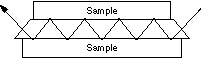
into a less-dense medium (with a lower refractive index). The fraction of the incident beam reflectedincreases when the angle of incidence increases. All incident radiation is completely reflected at the in-terface when the angle of incidence is greater than the critical angle (a function of refractive index). Thebeam penetrates a very short distance beyond the interface and into the less-dense medium before thecomplete reflection occurs. This penetration is called the evanescent wave and typically is at a depth ofa few micrometers (µm). Its intensity is reduced (attenuated) by the sample in regions of the IR spec-trum where the sample absorbs. Figure 15.11 illustrates the basic ATR principles.
The sample is normally placed in close contact with a more-dense, high-refractive-index crystal
such as zinc selenide, thallium bromide–thallium iodide (KRS-5), or germanium. The IR beam is di-rected onto the beveled edge of the ATR crystal and internally reflected through the crystal with a singleor multiple reflections. Both the number of reflections and the penetration depth decrease with increas-ing angle of incidence. For a given angle, the higher length-to-thickness ratio of the ATR crystal giveshigher numbers of reflections. A variety of types of ATR accessories are available, such as 25 to 75°vertical variable-angle ATR, horizontal ATR, and Spectra-Tech Cylindrical Internal Reflectance Cell
Handbook of Instrumental Techniques for Analytical Chemistry
for Liquid Evaluation (CIRCLE®) cell.
The resulting ATR-IR spectrum resembles the conventional IR spectrum, but with some differenc-
es: The absorption band positions are identical in the two spectra, but the relative intensities of corre-sponding bands are different. Although ATR spectra can be obtained using either dispersive or FTinstruments, FTIR spectrometers permit higher-quality spectra to be obtained in this energy-limited sit-uation.
Specular reflectance provides a nondestructive method for measuring thin coatings on selective,
smooth substrates without sample preparation. It basically involves a mirrorlike reflection and producesreflection measurements for a reflective material, or a reflection–absorption spectrum for the surfacefilm on a reflective surface. Thin surface coatings in the range from nanometers to micrometers can beroutinely examined with a grazing angle (typically 70 to 85°) or 30° angle of incidence, respectively. For example, lubricant thickness on magnetic media or computer disks is conveniently measured usingthis technique.
Diffuse reflectance technique is mainly used for acquiring IR spectra of powders and rough surface
solids such as coal, paper, and cloth. It can be used as an alternative to pressed-pellet or mull techniques. IR radiation is focused onto the surface of a solid sample in a cup and results in two types of reflections:specular reflectance, which directly reflects off the surface and has equal angles of incidence and re-flectance, and diffuse reflectance, which penetrates into the sample, then scatters in all directions. Spe-cial reflection accessories are designed to collect and refocus the resulting diffusely scattered light bylarge ellipsoidal mirrors, while minimizing or eliminating the specular reflectance, which complicatesand distorts the IR spectra. This energy-limited technique was not popular until the advent of FTIR in-struments. This technique is often called diffuse reflectance infrared Fourier transform spectroscopy(DRIFTS).
The sample can be analyzed either directly in bulk form or as dispersions in IR-transparent matrices
such as KBr and KCl. Dilution of analyte in a nonabsorbing matrix increases the proportion of diffuse re-flectance in all the light reflected. Typically the solid sample is diluted homogeneously to 5 to 10% byweight in KBr. The spectra of diluted samples are similar to those obtained from pellets when plotted inunits such as log 1/R (R is the reflectance) or Kubelka–Munk units. The Kubelka–Munk format relatessample concentration to diffuse reflectance and applies a scattering factor.
Photoacoustic spectroscopy (PAS) is a useful extension of IR spectroscopy and suitable for exam-
ining highly absorbing samples that are difficult to analyze by conventional IR techniques. The size andshape of the sample are not critical. PAS spectra can be obtained with minimal sample preparation andwithout physical alteration from a wide variety of samples such as powders, polymer pellets, viscousglues, single crystals, and single fibers.
Typically, the modulated IR radiation from an FTIR interferometer is focused on a sample placed
Figure 15.11 Schematic representation of multiple internal reflection effect in Attenuated Total Reflectance (ATR). (Reprinted from 1988 Annual Book of ASTM Standards by permission of American Society for Testing and Materials.)
in a small cup inside a small chamber containing an IR-transparent gas such as helium or nitrogen. IRradiation absorbed by the sample converts into heat inside the sample. The heat diffuses to the samplesurface, then into the surrounding gas atmosphere, and causes expansion of a boundary layer of gas nextto the sample surface. Thus, the modulated IR radiation produces intermittent thermal expansion of theboundary layer and generates pressure waves. A sensitive microphone is used to detect the resultingphotoacoustic signal.
PAS spectra are generally similar to conventional IR spectra except for some minor differences:
Absorbance peaks appear at the same frequency locations, but truncation of strong absorbance bandsdue to photoacoustic signal saturation is often observed. However, the presence of such truncated bandsdoes not limit the practical use of PAS. Spectral search against standard commercial spectral librariescan be satisfactorily performed. FTIR PAS technique also offers a unique capability for examiningsamples at various depths from 1 to 20 µm. The acoustic frequencies depend on the modulated frequen-cy of source: The slower the modulation frequency, the greater depth of penetration. Thus, samplessuch as multilayer polymers can be studied at various depths by simply varying the scan speed of theFTIR spectrometer.
Emission spectroscopy is another technique used with difficult samples such as thin coatings and
opaque materials. The sample is normally heated to an elevated temperature, emitting enough energy tobe detected. The sample acts as the radiation source, so the normal IR source is turned off. The ability ofFTIR instruments to obtain spectra from weak signals makes it possible to study emisssion in the infraredregion, even when the sample is at low temperatures such as 50 to 100 °C. Emission spectral bands occurat the same frequencies as absorption bands. The spectra from thick samples can be complicated whenradiation from the interior of the sample is self-absorbed by the outer part of the sample.
Infrared microspectroscopy has become a popular technique for analyzing difficult or small sam-
ples such as trace contaminants in semiconductor processing, multilayer laminates, surface defects, andforensic samples. Infrared microscopes are energy-inefficient accessories that require the signal-to-noise advantages of FTIR to obtain spectra from submilligram samples. Using a liquid nitrogen cooledmercury cadmium telluride (MCT) detector, samples in the size range of 10 µm can be examined on IRmicroscopes.
The primary advantages of the IR microscope relate not only to its improved optical and mechan-
ical design, but also to its manipulative capability. In many cases, the major problem in microsamplingis focusing the spectrometer beam on the sample. The computerized/motorized control of microscopefunctions of IR microscope instruments permit these extremely small samples to be moved in thefield of view to isolate the portion from which spectra are obtained.
Fiberoptic accessories deliver unique flexibility and diversity in sampling. They are particularly
useful in acquiring IR spectra when samples are situated in a remote location or when the unusual sizeor shape of samples prevents them from fitting well in a standard sample compartment. Many analysesin hazardous or process environments used these devices.
Fiberoptic sample probes or flow cells are coupled to standard FTIR spectrometers with two fi-
beroptic cables and an optic interface that transfers IR radiation from spectrometer to fiberoptic cables. A variety of probes are available for ATR, specular reflectance, diffuse reflectance, and transmittancemeasurements. Chalcogenide (GeAsSeTe), a mid IR–transmitting material in the range of 4000 to 900cm–1 , was recently developed by Spectra-Tech and used to make the fiberoptic cables.
Gas chromatography/Fourier transform infrared (GC/FTIR) spectroscopy is a technique that uses a gaschromatograph to separate the components of sample mixtures and an FTIR spectrometer to provideidentification or structural information on these components. The real potential of GC-IR instrumenta-
TOENAIL FUNGUS What is Toenail Fungus? Onychomycosis (toenail fungus) is an infection of the nail and sometimes surrounding tissue. It is extremely common with 20% of the general population and 75% of individuals over 60 years old affected. Frequently the problem causes cosmetic concerns, but many patients also experience pain, and infrequently toenail fungus can allow more serious inf
CORNWALL STARS CHEERLEADING & TRAMPOLINING CLUB Child Consent Form Participant’s name: ………………………………………… Date of Birth ………………………… MEDICAL INFORMATION ABOUT YOUR CHILD Does your child suffer from a medical condition/allergies? Yes If yes please give brief details (e.g. Asthma – takes ventolin, Diabetes – takes i
 • Identification of all types of organic and many types of inorganic compounds
• Determination of functional groups in organic materials
• Determination of the molecular composition of surfaces
• Identification of chromatographic effluents
• Quantitative determination of compounds in mixtures
• Determination of molecular conformation (structural isomers) and stereochemistry (geometri-
• Determination of molecular orientation (polymers and solutions)
• Identification of compounds by matching spectrum of unknown compound with reference
• Identification of functional groups in unknown substances
Handbook of Instrumental Techniques for Analytical Chemistry
• Identification of reaction components and kinetic studies of reactions
• Identification of molecular orientation in polymer films
• Detection of molecular impurities or additives present in amounts of 1% and in some cases as
• Identification of polymers, plastics, and resins
• Analysis of formulations such as insecticides and copolymers
Almost any solid, liquid or gas sample can be analyzed. Many sampling accessories are available.
• Identification of all types of organic and many types of inorganic compounds
• Determination of functional groups in organic materials
• Determination of the molecular composition of surfaces
• Identification of chromatographic effluents
• Quantitative determination of compounds in mixtures
• Determination of molecular conformation (structural isomers) and stereochemistry (geometri-
• Determination of molecular orientation (polymers and solutions)
• Identification of compounds by matching spectrum of unknown compound with reference
• Identification of functional groups in unknown substances
Handbook of Instrumental Techniques for Analytical Chemistry
• Identification of reaction components and kinetic studies of reactions
• Identification of molecular orientation in polymer films
• Detection of molecular impurities or additives present in amounts of 1% and in some cases as
• Identification of polymers, plastics, and resins
• Analysis of formulations such as insecticides and copolymers
Almost any solid, liquid or gas sample can be analyzed. Many sampling accessories are available. In analysis of mixtures under favorable conditions, accuracy is greater than 1%. In routine analyses, itis ± 5%.
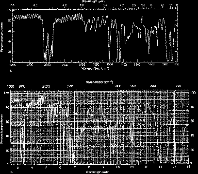 Handbook of Instrumental Techniques for Analytical Chemistry
Transmittance, T, is the ratio of radiant power transmitted by the sample (I) to the radiant power inci-dent on the sample (I0). Absorbance (A) is the logarithm to the base 10 of the reciprocal of the transmit-tance (T).
A = log (1 ⁄ T ) = –log T = –log I ⁄ I
The transmittance spectra provide better contrast between intensities of strong and weak bands be-
cause transmittance ranges from 0 to 100% T whereas absorbance ranges from infinity to zero. The an-alyst should be aware that the same sample will give quite different profiles for the IR spectrum, whichis linear in wavenumber, and the IR plot, which is linear in wavelength. It will appear as if some IRbands have been contracted or expanded.
Handbook of Instrumental Techniques for Analytical Chemistry
Transmittance, T, is the ratio of radiant power transmitted by the sample (I) to the radiant power inci-dent on the sample (I0). Absorbance (A) is the logarithm to the base 10 of the reciprocal of the transmit-tance (T).
A = log (1 ⁄ T ) = –log T = –log I ⁄ I
The transmittance spectra provide better contrast between intensities of strong and weak bands be-
cause transmittance ranges from 0 to 100% T whereas absorbance ranges from infinity to zero. The an-alyst should be aware that the same sample will give quite different profiles for the IR spectrum, whichis linear in wavenumber, and the IR plot, which is linear in wavelength. It will appear as if some IRbands have been contracted or expanded.
 Handbook of Instrumental Techniques for Analytical Chemistry
Figure 15.2 Major vibrational modes for a nonlinear group, CH2. (+ indicates motion from the plane of page to-ward reader; – indicates motion from the plane of page away from reader.) (Reprinted from R. M. Silverstein, G. C. Bassler, and T. C. Morrill, Spectrometric Identification of Organic Compounds, 4th edition. New York: John Wiley & Sons, 1981, p. 166, by permission of John Wiley & Sons, Inc., copyright 1981.)
In simple terms, IR spectra are obtained by detecting changes in transmittance (or absorption) intensityas a function of frequency. Most commercial instruments separate and measure IR radiation using dis-persive spectrometers or Fourier transform spectrometers.
Handbook of Instrumental Techniques for Analytical Chemistry
Figure 15.2 Major vibrational modes for a nonlinear group, CH2. (+ indicates motion from the plane of page to-ward reader; – indicates motion from the plane of page away from reader.) (Reprinted from R. M. Silverstein, G. C. Bassler, and T. C. Morrill, Spectrometric Identification of Organic Compounds, 4th edition. New York: John Wiley & Sons, 1981, p. 166, by permission of John Wiley & Sons, Inc., copyright 1981.)
In simple terms, IR spectra are obtained by detecting changes in transmittance (or absorption) intensityas a function of frequency. Most commercial instruments separate and measure IR radiation using dis-persive spectrometers or Fourier transform spectrometers.
 Dispersive spectrometers, introduced in the mid-1940s and widely used since, provided the robust in-strumentation required for the extensive application of this technique.
An IR spectrometer consists of three basic components: radiation source, monochromator, and detector.
Dispersive spectrometers, introduced in the mid-1940s and widely used since, provided the robust in-strumentation required for the extensive application of this technique.
An IR spectrometer consists of three basic components: radiation source, monochromator, and detector.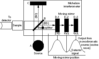
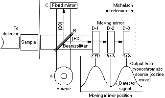 Figure 15.4 Simplified optical layout of a typical FTIR spectrometer. (Reprinted by permission of Nicolet Instrument Corporation.)
changes in the relative position of the moving mirror to the fixed mirror, an interference pattern is gen-erated. The resulting beam then passes through the sample and is eventually focused on the detector.
For an easier explanation, the detector response for a single-frequency component from the IR
source is first considered. This simulates an idealized situation where the source is monochromatic, suchas a laser source. As previously described, differences in the optical paths between the two split beamsare created by varying the relative position of moving mirror to the fixed mirror. If the two arms of theinterferometer are of equal length, the two split beams travel through the exact same path length. Thetwo beams are totally in phase with each other; thus, they interfere constructively and lead to a maxi-mum in the detector response. This position of the moving mirror is called the point of zero path differ-ence (ZPD). When the moving mirror travels in either direction by the distance λ/4, the optical path(beamsplitter–mirror–beamsplitter) is changed by 2 (λ/4), or λ/2. The two beams are 180° out of phasewith each other, and thus interfere destructively. As the moving mirror travels another λ/4, the opticalpath difference is now 2 (λ/2), or λ. The two beams are again in phase with each other and result in an-other constructive interference.
When the mirror is moved at a constant velocity, the intensity of radiation reaching the detector
varies in a sinusoidal manner to produce the interferogram output shown in Fig. 15.4. The interferogramis the record of the interference signal. It is actually a time domain spectrum and records the detectorresponse changes versus time within the mirror scan. If the sample happens to absorb at this frequency,the amplitude of the sinusoidal wave is reduced by an amount proportional to the amount of sample inthe beam.
Figure 15.4 Simplified optical layout of a typical FTIR spectrometer. (Reprinted by permission of Nicolet Instrument Corporation.)
changes in the relative position of the moving mirror to the fixed mirror, an interference pattern is gen-erated. The resulting beam then passes through the sample and is eventually focused on the detector.
For an easier explanation, the detector response for a single-frequency component from the IR
source is first considered. This simulates an idealized situation where the source is monochromatic, suchas a laser source. As previously described, differences in the optical paths between the two split beamsare created by varying the relative position of moving mirror to the fixed mirror. If the two arms of theinterferometer are of equal length, the two split beams travel through the exact same path length. Thetwo beams are totally in phase with each other; thus, they interfere constructively and lead to a maxi-mum in the detector response. This position of the moving mirror is called the point of zero path differ-ence (ZPD). When the moving mirror travels in either direction by the distance λ/4, the optical path(beamsplitter–mirror–beamsplitter) is changed by 2 (λ/4), or λ/2. The two beams are 180° out of phasewith each other, and thus interfere destructively. As the moving mirror travels another λ/4, the opticalpath difference is now 2 (λ/2), or λ. The two beams are again in phase with each other and result in an-other constructive interference.
When the mirror is moved at a constant velocity, the intensity of radiation reaching the detector
varies in a sinusoidal manner to produce the interferogram output shown in Fig. 15.4. The interferogramis the record of the interference signal. It is actually a time domain spectrum and records the detectorresponse changes versus time within the mirror scan. If the sample happens to absorb at this frequency,the amplitude of the sinusoidal wave is reduced by an amount proportional to the amount of sample inthe beam.
 Handbook of Instrumental Techniques for Analytical Chemistry
Figure 15.5 Interferogram consisting of three modulated cosine waves. The greatest amplitude occurs at the point of zero path difference (ZPD). (Reprinted by permission of Nicolet Instrument Corporation.)
sive. A mathematical operation known as Fourier transformation converts the interferogram (a time do-main spectrum displaying intensity versus time within the mirror scan) to the final IR spectrum, whichis the familiar frequency domain spectrum showing intensity versus frequency. This also explains howthe term Fourier transform infrared spectrometry is created.
The detector signal is sampled at small, precise intervals during the mirror scan. The sampling rate
is controlled by an internal, independent reference, a modulated monochromatic beam from a heliumneon (HeNe) laser focused on a separate detector.
Handbook of Instrumental Techniques for Analytical Chemistry
Figure 15.5 Interferogram consisting of three modulated cosine waves. The greatest amplitude occurs at the point of zero path difference (ZPD). (Reprinted by permission of Nicolet Instrument Corporation.)
sive. A mathematical operation known as Fourier transformation converts the interferogram (a time do-main spectrum displaying intensity versus time within the mirror scan) to the final IR spectrum, whichis the familiar frequency domain spectrum showing intensity versus frequency. This also explains howthe term Fourier transform infrared spectrometry is created.
The detector signal is sampled at small, precise intervals during the mirror scan. The sampling rate
is controlled by an internal, independent reference, a modulated monochromatic beam from a heliumneon (HeNe) laser focused on a separate detector.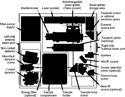
 more sensitive than the DTGS detector.
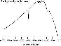


 Handbook of Instrumental Techniques for Analytical Chemistry
Figure 15.8 A single-beam IR spectrum of background, showing contribution from trace amount of ambient water and carbon dioxide.
Handbook of Instrumental Techniques for Analytical Chemistry
Figure 15.8 A single-beam IR spectrum of background, showing contribution from trace amount of ambient water and carbon dioxide.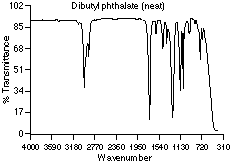
 Figure 15.10 The “double-beam” IR spectrum of dibutyl phthalate, produced by ratio of the corresponding single-beam sample spectrum against the single-beam background spectrum.
 Handbook of Instrumental Techniques for Analytical Chemistry
It is possible to obtain an IR spectrum from samples in many different forms, such as liquid, solid, andgas. However, many materials are opaque to IR radiation and must be dissolved or diluted in a trans-parent matrix in order to obtain spectra. Alternatively, it is possible to obtain reflectance or emissionspectra directly from opaque samples. Some popular sampling techniques and accessories are discussedhere.
Handbook of Instrumental Techniques for Analytical Chemistry
It is possible to obtain an IR spectrum from samples in many different forms, such as liquid, solid, andgas. However, many materials are opaque to IR radiation and must be dissolved or diluted in a trans-parent matrix in order to obtain spectra. Alternatively, it is possible to obtain reflectance or emissionspectra directly from opaque samples. Some popular sampling techniques and accessories are discussedhere.
 Handbook of Instrumental Techniques for Analytical Chemistry
for Liquid Evaluation (CIRCLE®) cell.
Handbook of Instrumental Techniques for Analytical Chemistry
for Liquid Evaluation (CIRCLE®) cell.